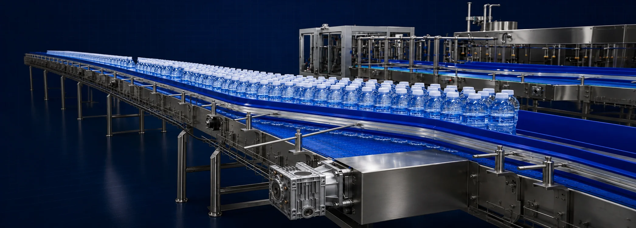
Stainless-steel conveyor systems for bottles and cans, with modular belts, adjustable guide rails and drive controls configured for your production line.
Stainless-steel frames, matched drive components and adjustable guides connect each stage of your bottle or can line.
Frame material
SUS304
Drive power
0.75–1.5 kW
Minimum curve radius
500 mm
Guide rails
Height & width adjustable
01
Frame & support
The structure behind a stable, continuous conveying route.
Side panels
Form the stainless-steel sides of the conveyor frame.
SUS304 · 2.5 mm
Specifications
Material
SUS304
Panel thickness
2.5 mm
Panel height: 160 mm.
Cross braces
Support the frame across the conveyor width.
SUS304 · 2.0–3.0 mm
Specifications
Material
SUS304
Plate thickness
2.0–3.0 mm
Brace thickness is selected to suit the conveyor configuration.
End plates: 5 mm thick with M10 threaded holes.
Cross-brace spacing: approximately 500 mm.
Connecting plates
Join adjacent conveyor sections.
SUS304 · 2.5 mm
Specifications
Material
SUS304
Plate thickness
2.5 mm
Support legs
Set the conveyor height with braced, adjustable supports.
50 × 50 mm tube · adjustable foot
Specifications
Square tube
50 × 50 × 1.5 mm
Foot screw
M16 × 100
SUS304 construction with 4 mm support connection plates.
Plastic foot plate: 100 mm diameter.
Diagonal bracing is selected according to support height.
The updated leg design uses laser-cut square tubes and brace or tube-lock connections.
Roller shafts
Support the rollers with lightweight stainless-steel tubes.
SUS304 · Ø19 × 2 mm
Specifications
Material
SUS304
Tube size
Ø19 × 2 mm
Rivet nuts are fitted at both ends of the tube.
Transfer guides
Guide the chain smoothly between rails and sprockets.
SUS304 · 5 mm
Specifications
Material
SUS304
Plate thickness
5 mm
Mounted at the support-rail ends and secured with inserted screws.
The guided transition helps reduce noise at the chain and sprocket junction.
02
Drive & transfer
Matched shafts, belts and drives keep the line moving.
Drive shafts
Transmit the drive through removable, ground steel shafts.
2Cr13 steel · Ø40 mm
Specifications
Material
2Cr13
Shaft diameter
40 mm
Ground surface finish.
Mounting arrangement allows disassembly and replacement.
Bearing units
Support the shaft in a removable bearing housing.
Removable mounting
Specifications
Mounting
Removable
Support rollers
Cushion chain travel to reduce noise and wear.
PE core · TPE surface
Specifications
Roller core
PE
Outer layer
TPE
The TPE contact surface cushions the chain as it travels over the rollers.
Modular belting
Carry containers through straight runs and magnetic curves.
1600 straight · 1060 turning
Specifications
Straight sections
1600 series
Turning sections
1060 series
Nominal chain thickness: 8.7 mm.
Turning-chain width: 83.8 mm, with a magnetic guide rail.
Minimum turning radius: 500 mm.
Chain brand: Xingbaolai or an equivalent domestic supplier.
Drive & idler sprockets
Engage the chain with easily assembled split sprockets.
PA66 · split construction
Specifications
Material
PA66
Drive sprocket
Injection-moulded, split
Idler sprockets are available in split or one-piece construction.
Geared motor
Power the conveyor with a compact geared drive.
0.75–1.5 kW
Specifications
Motor power
0.75–1.5 kW
Gear reducer
Minghua or equivalent
Power selection depends on the conveyor application.
Compact installation and low-noise operation.
03
Guiding & control
Container guidance, drainage and coordinated drive control.
Rail brackets
Adjust guide-rail height and width to the container.
SUS304 · height & width adjustment
Specifications
Material
SUS304
Holder thickness
4 mm
Guardrail support tube: Ø20 × 1.5 mm.
Support rod diameter: 12–16 mm; length depends on the conveyor layout.
Cast connecting pieces secure the support rods.
Rail height and rod length are selected for the container format.
Container guides
Keep bottles and cans aligned along the conveyor.
UHMW-PE · aluminium support
Specifications
Rail material
UHMW-PE
Profile support
Aluminium alloy
Profile supports are fixed with connecting plates and bolts.
Rail options include large C profiles and ST-100 wide rails.
Can conveyors use double-level round guide rails on stainless-steel connecting plates.
Rail positions are adjusted to support the stronger areas of the bottle or can.
Wear strips & rails
Support chain travel while protecting the conveyor frame.
Wear-resistant polymer · SUS304 rails
Specifications
Wear strips
Engineering plastic
SUS304 support tube
30 × 20 × 1.5 mm
Side-panel wear strips use clip-on Z-shaped or L-shaped profiles.
Riveted ends secure the wear strips to the side panels.
Support-rail spacing is selected for smooth transfer, including stainless-steel chain applications.
Magnetic curves
Hold the chain securely through a change of direction.
UHMW-PE · R500 mm minimum
Specifications
Guide material
UHMW-PE 1000 grade
Minimum radius
500 mm
Track pitch: 85 mm.
Material molecular weight: greater than 4 million g/mol.
Guide supplier: Dongze Machinery.
Magnetic retention supports stable chain travel through the curve.
Drain trays & brackets
Collect water and lubricant beneath the conveyor.
SUS304 · 1 mm tray
Specifications
SUS304 tray thickness
1 mm
Cleaning clearance
At least 50 mm
U-shaped or M-shaped trays use suspended mounting.
Wide conveyor sections use additional tray supports and reinforcement.
Drainage direction follows the line layout and connects to the customer’s drainage system.
Control cabinet
Coordinate conveyor drives with PLC and inverter controls.
Inovance PLC & inverter
Specifications
PLC
Inovance
Inverter
Inovance
Circuit breaker: Schneider.
Gear reducer: Minghua.
Chain belt: Xingbaolai.
Final component selection is confirmed for each project.
Project configuration. Conveyor width, height, routing and component selection are configured for each project. Final specifications are confirmed against the production-line layout and bottle or can format.
Line integration
Plan the conveyor route.
Send your bottle or can dimensions, target output, conveyor height and available floor plan so we can configure the route and drive system.