Filter · RO · Disinfect / Bottled & process water

Water Treatment System

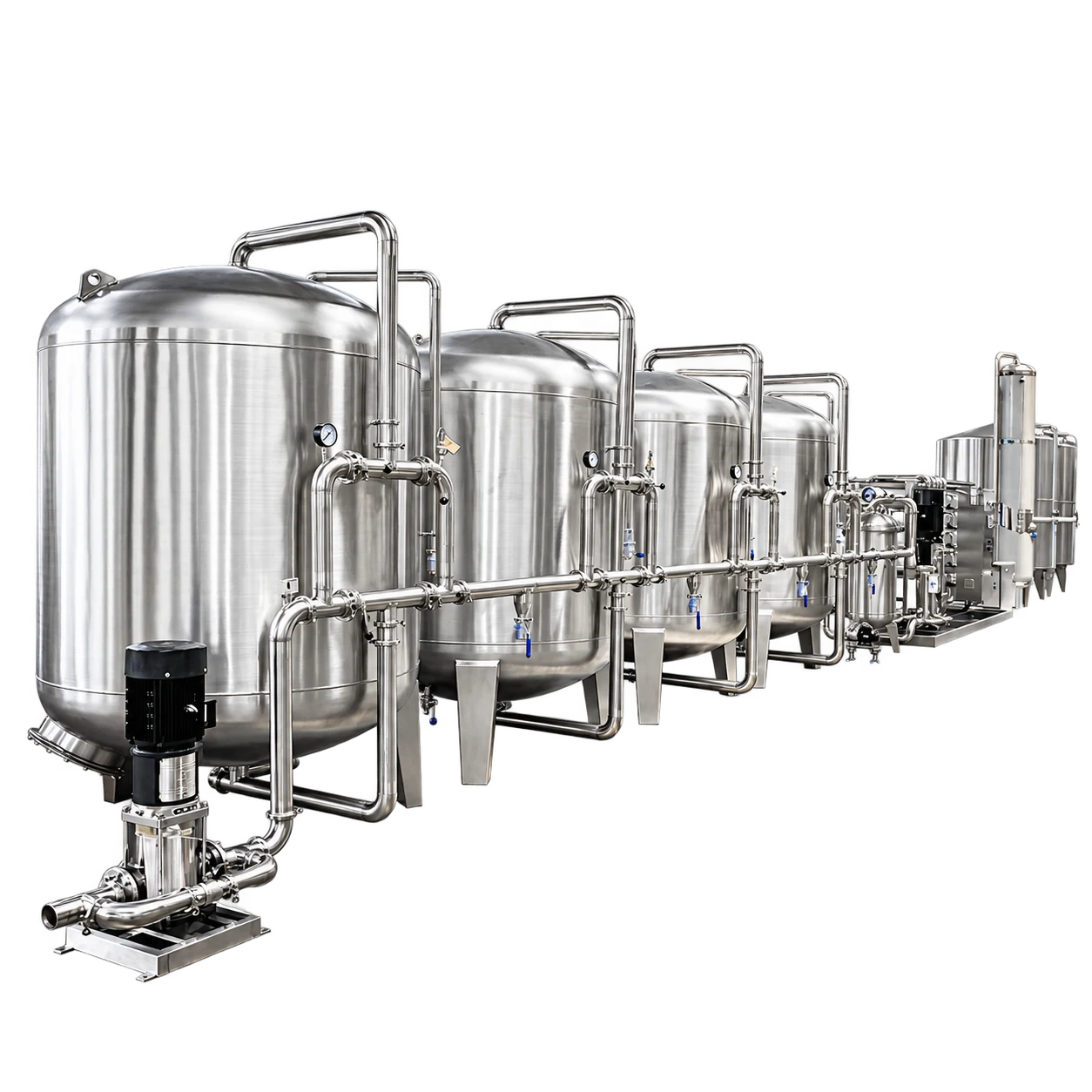
A complete purification route for bottled water and beverage process water, from raw-water pump to pure-water tank. Each stage is sized to the source-water report and the finished-water target.

Route
9 stages
Capacity range
0.5–30 T/h
Contact parts
SUS304 / SUS316

Treatment route

From source water to pure water.

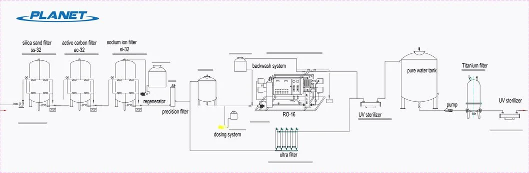
9 stages in three phases. Select a stage to see its role and configuration options.

  1. Phase 1 · Pre-treatment

  2. Phase 2 · Membrane

  3. Phase 3 · Disinfection & storage

Stage 06 · Membrane

Reverse osmosis system

Uses membrane separation to reduce dissolved salts and produce water for bottled-water and beverage applications. Source-water analysis and finished-water quality requirements guide membrane selection and process configuration.

View equipment details

Customizable configuration

Feed and permeate flow, recovery target, membrane arrangement and pump selection are configurable. The skid footprint, controls and cleaning arrangement are specified around the required output and site layout.

Factory footage · 30 T/h RO system

Walk the route on a real installation.

Water treatment system layout: sand, carbon and sodium-ion filters, regenerator, precision filter, RO, UV sterilizer and pure water tank
LINE PLANEquipment layoutOpen full image ↗

Project-specific configuration

Configured for your process.

Equipment selection follows your source-water analysis, finished-water requirements and production demand. Capacity, dimensions and configuration are confirmed for each project.

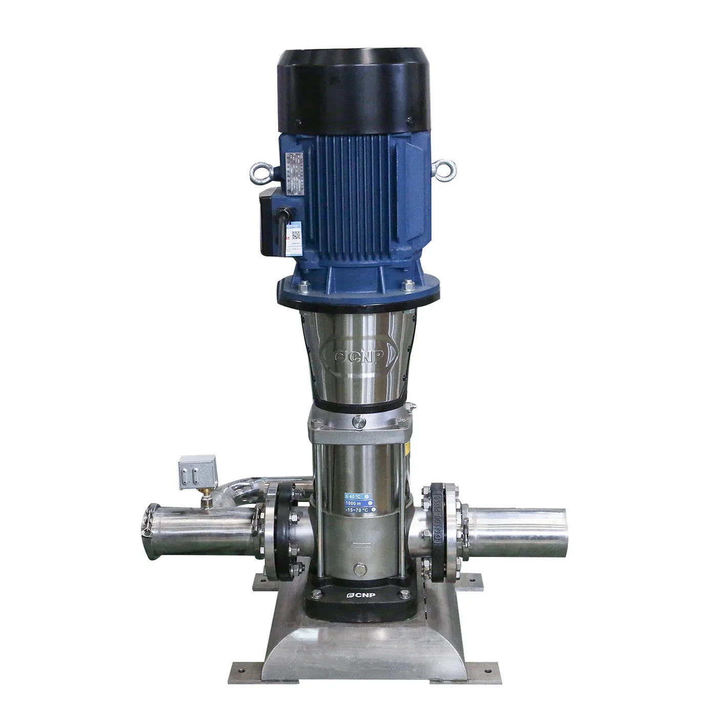
Vertical multistage stainless-steel raw water pump

01Pre-treatment

Raw water pump

Feeds source water into the treatment train at a stable flow and pressure.

Brand
CNP · Grundfos optional
Flow
12 T/h
Motor power
Customizable
Speed
2,900 rpm
Inlet
Ø50 mm inner diameter
Max. operating pressure
10 bar
Liquid temperature
Standard −15 to +70 °C · hot-water type +70 to +110 °C
Max. ambient
+40 °C

Maximum inlet pressure is limited by the maximum operating pressure. Liquid temperature to be confirmed per project.
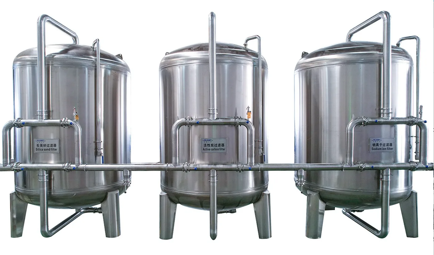
Three stainless-steel vessels for silica sand filtration, activated carbon filtration and sodium ion exchange, from left to right
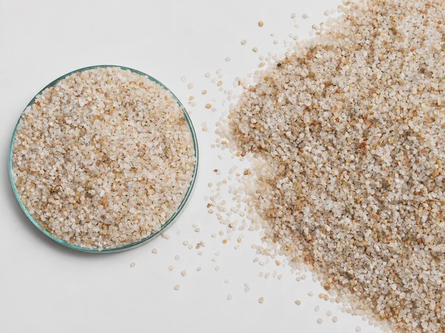
  • Quartz sand filter media in a glass dish and loose granulesQuartz sand
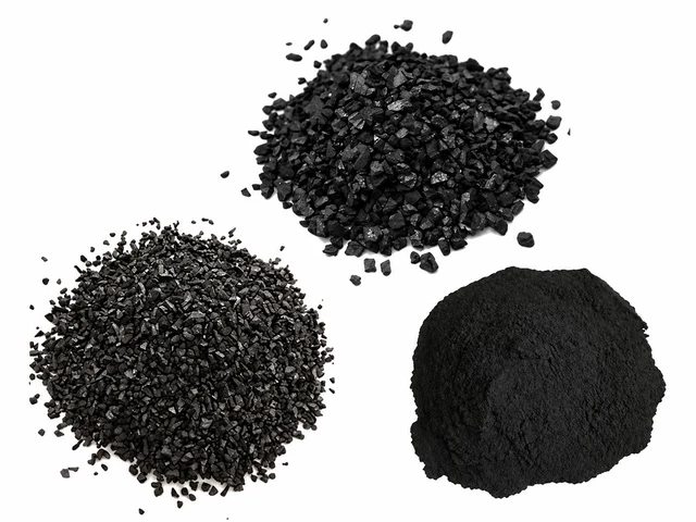
  • Coarse, granular and powdered activated carbon filter mediaActivated carbon
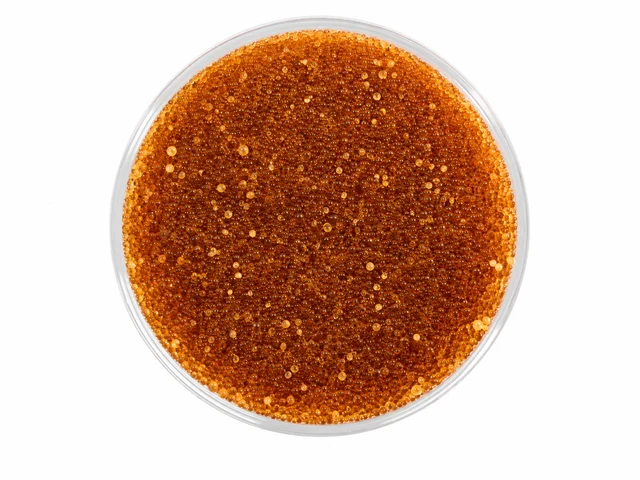
  • Amber ion-exchange resin beads in a glass dish for water softeningIon-exchange resin

02–04Pre-treatment

Filtration & softening

  1. Silica sand filter

    Graded silica sand removes suspended solids and sediment before downstream treatment. Manual-valve backwashing restores the filter bed.

  2. Active carbon filter

    Shell-type activated carbon adsorbs colour, odour, residual chlorine and organic compounds, protecting the treatment stages downstream.

  3. Sodium ion exchanger

    Cation-exchange resin removes calcium and magnesium ions to soften the water and reduce scaling on the RO membranes. Brine regeneration restores the resin.

Capacity
Customizable
Vessel
Customizable
Material
SUS304 food grade (SUS316 optional)
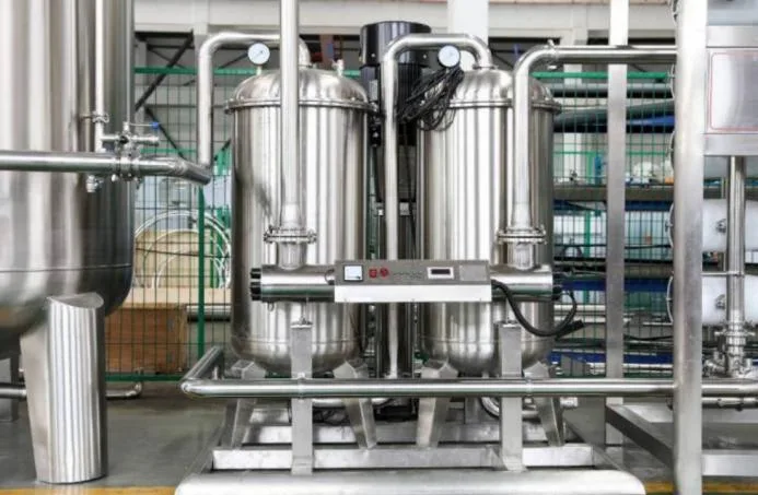
Twin stainless-steel precision filter housings on a treatment skid
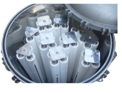
  • Filter cartridges inside an open precision filter housingFilter cartridges

05Pre-treatment

Precision filter

Captures fine suspended particles and traces of filter media before water enters the RO system. The cartridge housing provides a final filtration step after sand, carbon and softening treatment, helping protect the downstream membranes.

Customizable configuration

Filtration rating, cartridge quantity, housing size and pipe connections are selected to match source-water conditions and required flow. Materials and operating limits are confirmed for each installation.

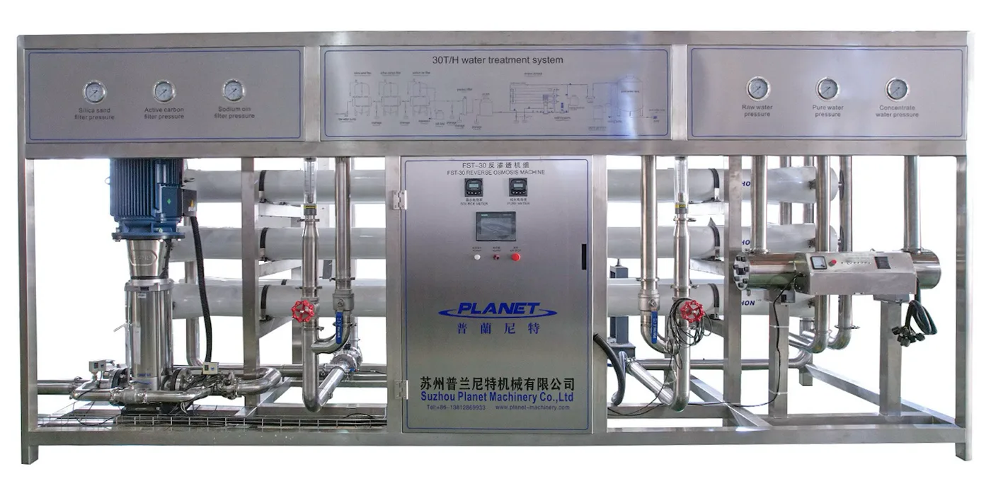
Reverse osmosis skid with high-pressure pump, membrane housings and control cabinet

06Membrane

Reverse osmosis system

Uses membrane separation to reduce dissolved salts and produce water for bottled-water and beverage applications. Source-water analysis and finished-water quality requirements guide membrane selection and process configuration.

Customizable configuration

Feed and permeate flow, recovery target, membrane arrangement and pump selection are configurable. The skid footprint, controls and cleaning arrangement are specified around the required output and site layout.

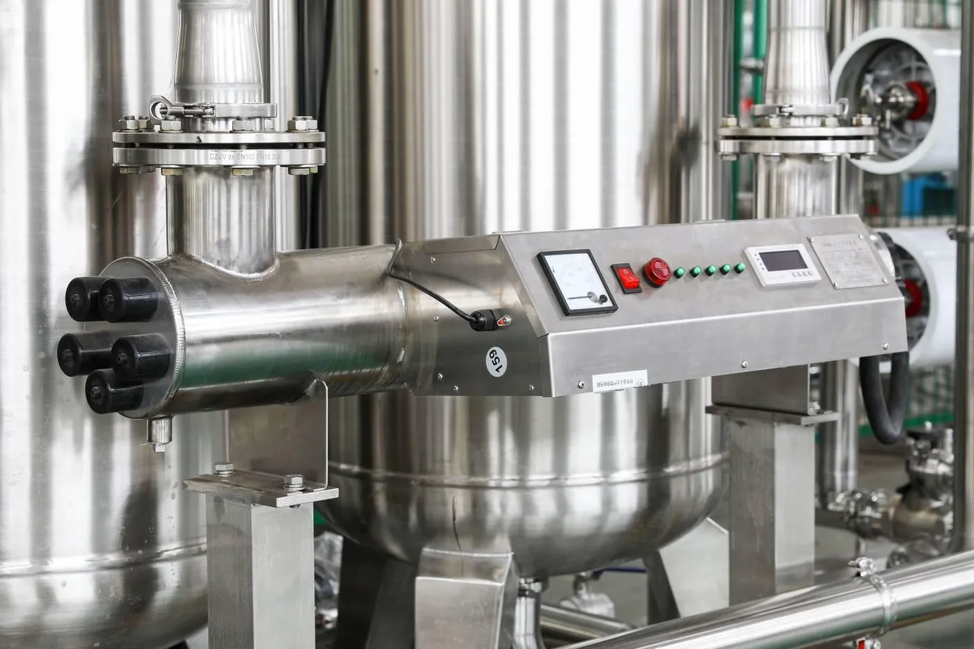
Stainless-steel UV sterilizer with control panel mounted on a treatment skid

07Disinfection & storage

UV sterilizer

Uses ultraviolet light to inactivate microorganisms as treated water passes through the reactor. It provides a disinfection step without chemical dosing, with the treatment duty determined from water quality and the downstream process.

Customizable configuration

Treatment flow, lamp power, UV dose and reactor dimensions are selected for the project. The configuration is matched to operating conditions and disinfection requirements, with lamp access and maintenance considered in the layout.

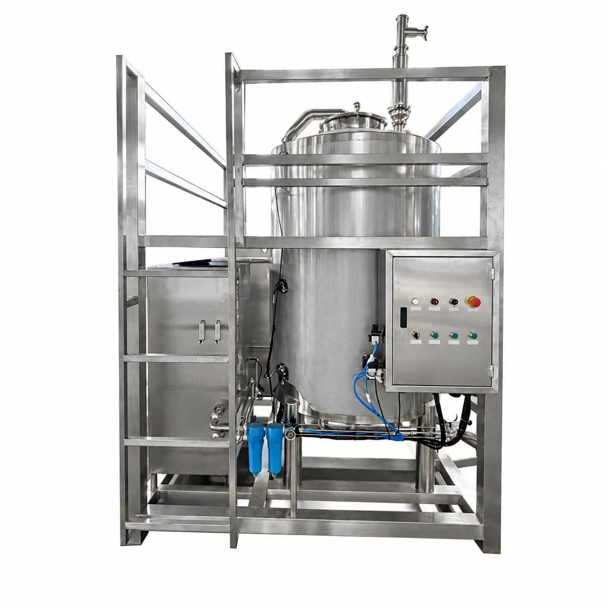
Stainless-steel ozone mixing system with tank, control cabinet and skid frame

08Disinfection & storage

Ozone mixing system

Combines ozone generation and mixing to introduce ozone into treated water before storage. Generator duty and contact conditions are coordinated with product-water flow and the required disinfection process.

Customizable configuration

Ozone output, oxygen supply, mixing-tank capacity and pump arrangement are customizable. System dimensions and pipe connections are planned to suit the treatment route and available installation space.

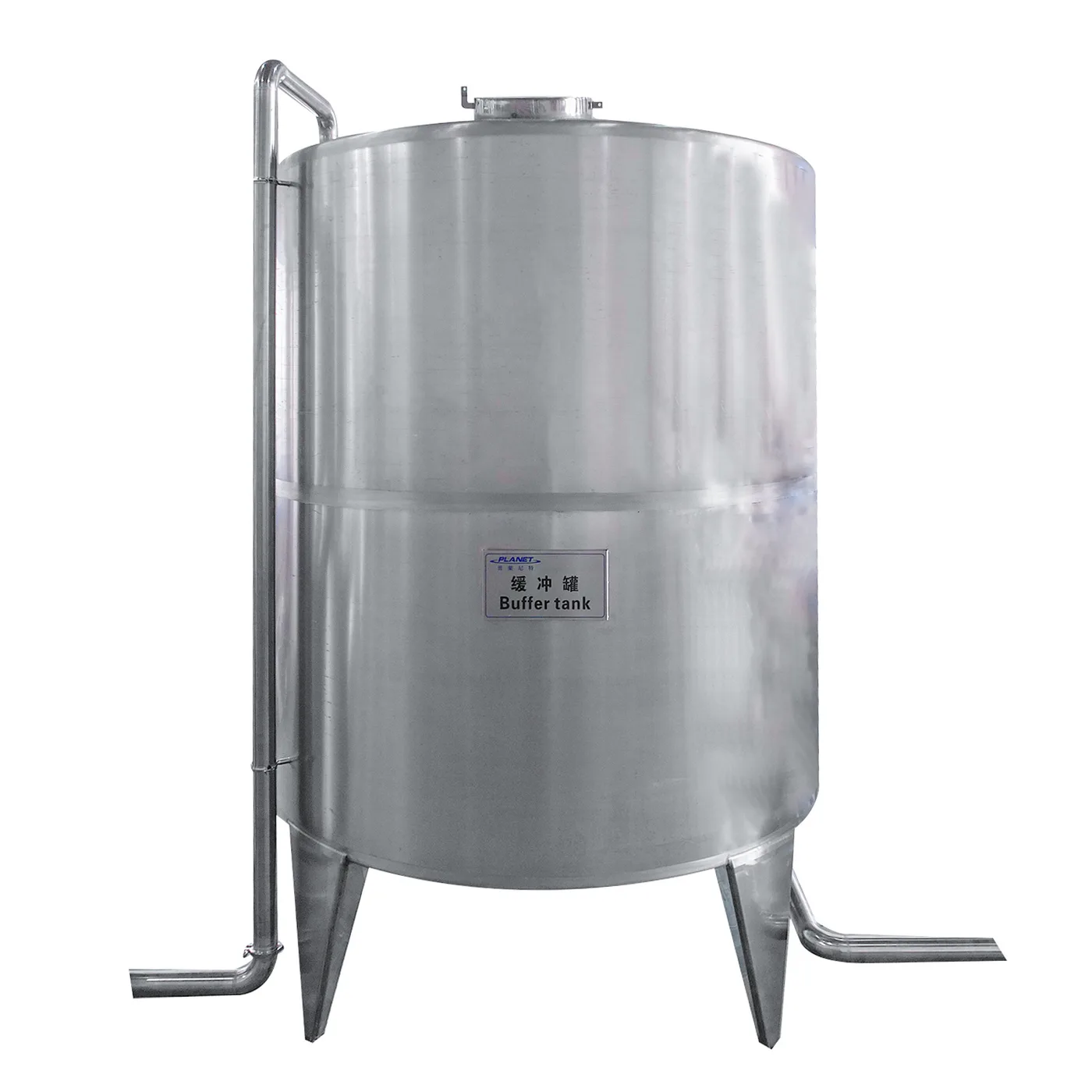
Vertical stainless-steel pure water storage tank on legs

09Disinfection & storage

Pure water tank

Provides a buffer of treated water between purification and filling. Tank size and layout are planned around filling demand and available floor space, with access for inspection, cleaning and drainage considered as part of the design.

Customizable configuration

Storage volume, vessel dimensions, wall thickness and pipe connections are customizable. Material selection, level indication and breather arrangement are confirmed for the project.

Published technical data

Choose the system capacity.

RO system sizes from 0.5 to 30 T/h. Power, footprint and weight are for the RO system; confirm the full route against your source water.

01

RO system capacity range

ModelCapacity (Ton Per hour)General powerSize(L*W*H)Weight (kg)
RO-500L/H0.5Ton0.75kw1550*900*1820mm350kg
RO-1000L/H1Ton1.5kw1980*900*1940mm500kg
RO-2000L/H2Ton2kw4800*700*2050mm700kg
RO-3000L/H3Ton5kw6000*800*2200mm800kg
RO-4000L/H4Ton6.5kw7000*900*2400mm1000kg
RO-5000L/H5Ton8kw8000*1000*2700mm1500kg
RO-6000L/H6Ton12kw8500*1600*1920mm2000kg
RO-8000L/H8Ton15kw10000*1870*3000mm4000kg
RO-10000L/H10Ton20kw12000*1700*3500mm4500kg
RO-15000L/H15Ton25kw12500*1700*3500mm6500kg
RO-20000L/H20Ton30kw13000*1900*3500mm9000kg
RO-30000L/H30Ton35kw13500*2300*3800mm12000kg

RO protection & control

Built to run unattended.

The RO protects itself, flushes after every stop and cleans in place, all from one control box.

  1. 01

    Pump protection

    Pressure switches on the high-pressure pump inlet and outlet. Low inlet pressure (≤ 0.05 MPa) or high outlet pressure (≥ 1.8 MPa) triggers an alarm and stops the pump automatically.

  2. 02

    Soft pressure build-up

    A valve on the high-pressure pump lets membrane pressure rise gradually, avoiding water-hammer damage.

  3. 03

    Automatic flushing

    A motorised concentrate valve runs a 10–20 min low-pressure flush each time the RO stops, plus regular high-flow flushing to limit fouling.

  4. 04

    Chemical cleaning

    A built-in CIP unit cleans the membranes when performance drops, restoring salt rejection and permeate output.

  5. 05

    Centralised control

    One process control box with automatic and manual modes, tank-level interlocks and online permeate-flow display.

  • Complete scope

    Equipment sized to the specified output and water quality, with design, supply, installation and commissioning until the system runs normally.

  • Recognised components

    Pumps, membranes and controls come from established brands.

  • Room to expand

    The route can be extended later if water-quality requirements rise.

  • Long-term stability

    Process parameters, equipment selection and controls are set for safe, stable and efficient operation.

Plan your water route

Start with your water report.

Share the source-water analysis, the required finished-water quality and the target flow. We will recommend the treatment stages and system size.

Request a proposal