Injection molding / PET preforms

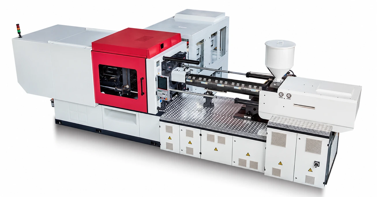
PET Preform Injection Molding System

A dedicated injection molding system for PET preforms used in water, carbonated beverage and edible-oil bottles. Match the injection unit, clamping force and mould to your preform design.

  • Water bottles
  • Carbonated beverages
  • Edible oil
Machine range
5 PET models
Clamping force
2,180–5,000 kN
PET screw design
25:1 L/D ratio

PET preform applications

It starts with
the right preform.

From drinking water to edible oil, the preform design defines the mould, injection capacity and machine configuration.

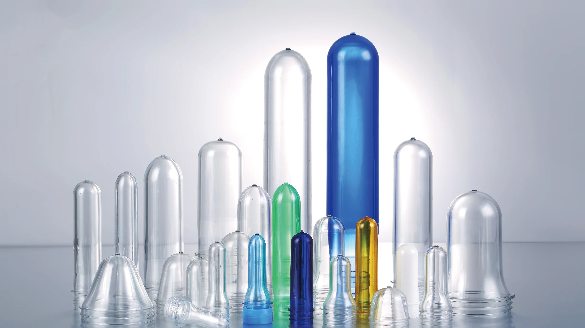
Clear and coloured PET preforms in a range of neck finishes and lengths
PET preform examples · final dimensions follow your bottle design
  1. 01

    Water bottles

    Transparent PET preforms for drinking-water bottles.

  2. 02

    Carbonated beverages

    PET preforms selected around the bottle and neck-finish design.

  3. 03

    Edible oil & larger formats

    Longer preforms supported by the extended ejector stroke; mould and machine selection depend on the preform geometry.

Inside the system

Designed around
the PET cycle.

Dedicated plasticizing, controlled injection and dependable mould handling work together through each production cycle.

Clamping built around the mould
01 / ENGINEERING

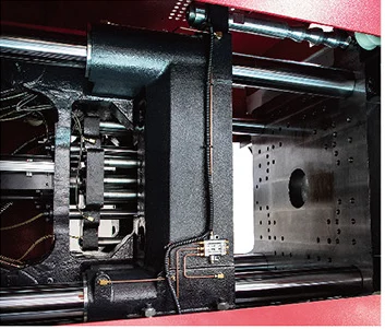
Clamping built around the mould

A rigid clamping structure with generous opening stroke and mould space accommodates different preform mould sizes. Extended ejector travel and dedicated ejector force support the release of longer preforms.
A screw designed for PET
02 / ENGINEERING

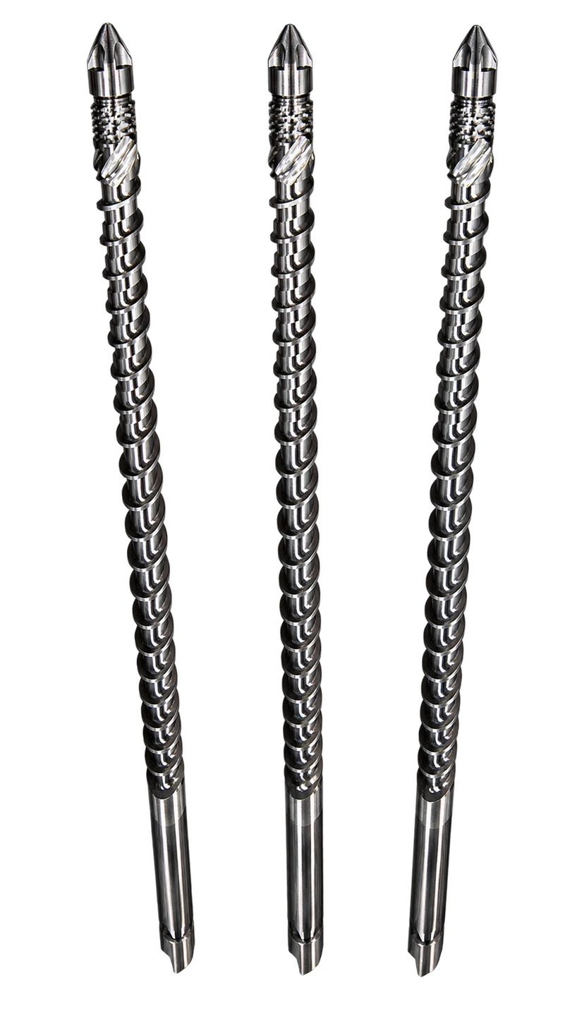
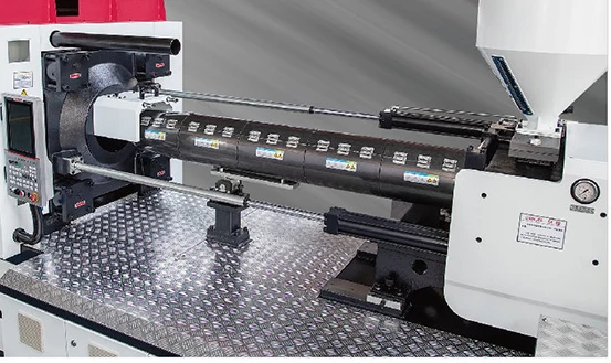
A screw designed for PET

Dedicated PET screw and barrel design with a 25:1 L/D ratio. Special materials and heat treatment support plasticizing, colour mixing and preform transparency.

Balanced twin-cylinder injection
03 / ENGINEERING

Balanced twin-cylinder injection

A twin-cylinder arrangement balances the injection drive. The oil circuit is designed to reduce return resistance and support stable high-pressure injection.

Guided, aligned movement
04 / ENGINEERING

Guided, aligned movement

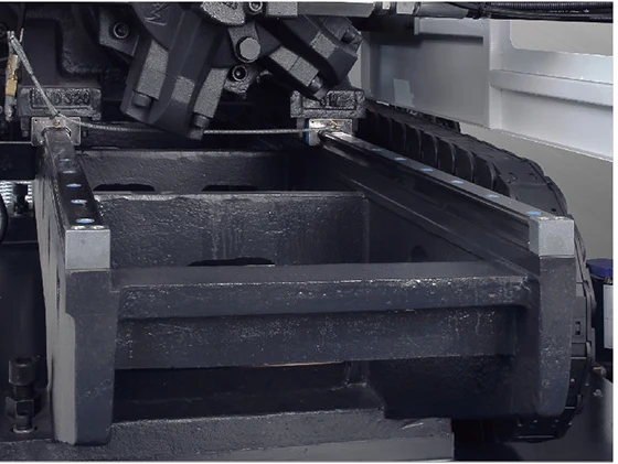
An integrated injection-unit carriage and linear guides keep movement aligned, reduce friction and support responsive injection control.

Hydraulics & lubrication
05 / ENGINEERING

Hydraulics & lubrication

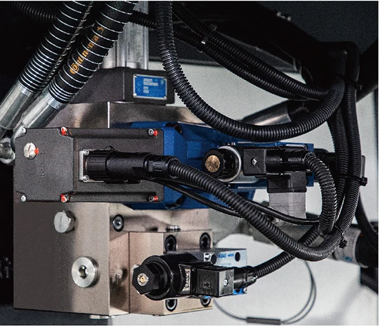
Fixed-point, metered lubrication supports reliable operation. A fast-closing hydraulic circuit and a reinforced hydraulic motor support clamping and plasticizing.

Control of the preform cycle
06 / ENGINEERING

Control of the preform cycle

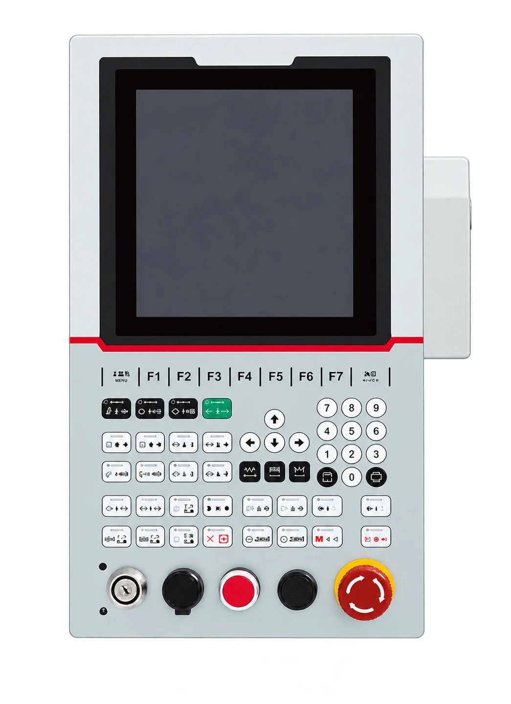
Adjustable mould needle-valve timing, screw speed and proportional back pressure. Mechanical, electrical and hydraulic protection work together, with interfaces for robotic handling and conveyors.

PET preform moulds

Match the mould
to the preform.

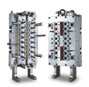
Choose cavity count and neck finish around preform weight, geometry and target output. Compatibility is checked against the selected machine.

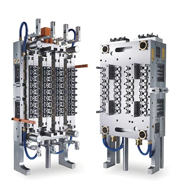
16-cavity PET preform mould
16Cavity preform mould
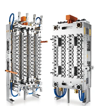
32-cavity PET preform mould
32Cavity preform mould
48-cavity PET preform mould
48Cavity preform mould
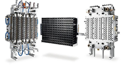
72-cavity PET preform mould
72Cavity preform mould
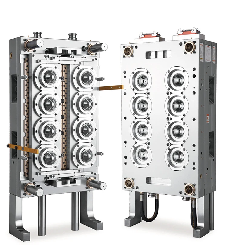
Wide-mouth PET jar preform mould

Additional mould format

Wide-mouth preforms.

A dedicated mould option for wide-mouth PET preforms. Share the neck finish, preform drawing and weight so the mould and injection unit can be matched together.

Discuss your mould

Five models / Configurable injection units

Find your
machine configuration.

Compare the range, then open a model for its complete specifications. Injection weight and screw size depend on the selected injection unit.

Swipe the table to compare models

PET injection machine model comparison
ModelPLT218PETPLT268PETPLT320PETPLT430PETPLT500PET
Clamping force kN2,1802,6803,2004,3005,000
Screw diameter mm60–6767–7575–10590–10595–125
Injection weight, PET g1,000–1,2471,290–1,6161,932–4,4873,297–4,4873,673–8,380
Tie-bar spacing mm · H × V530 × 530580 × 580680 × 680760 × 730830 × 830

Ranges cover the listed configurations; they are not a production-output rating.

PLT218PET

2,180 kN2 injection configurations

Swipe to compare injection configurations

PLT218PET technical specifications by injection unit and screw configuration
ParameterUnit1060/218
AØ 60 mmBØ 67 mm
Injection unit
Theoretical injection volumecm³cm³8201022
Injection weight (PET)gg10001247
Injection weight (PET)ozoz35.344
Injection rate (PET)g/sg/s381479
Screw diametermmmm6067
Injection pressureMPaMPa129104
Screw L/D ratio——25:125:1
Screw strokemmmm290290
Screw speedr/minr/min0–1580–158
Clamping unit
Clamping forcekNkN21802180
Mould opening strokemmmm510510
Platen sizemmmm780 × 780780 × 780
Tie-bar spacing (H × V)mmmm530 × 530530 × 530
Maximum daylightmmmm10601060
Mould thickness (min.–max.)mmmm200–550200–550
Ejector strokemmmm170170
Ejector forcekNkN9999
Power & heating
Hydraulic system pressureMPaMPa17.517.5
Pump motor powerkWkW31.331.3
Heater powerkWkW29.833.6
Temperature-control zones——66
Installation
Oil tank capacityLL420420
Machine dimensions (L × W × H)mm6.25 × 1.70 × 2.236.25 × 1.70 × 2.23
Machine weighttt88
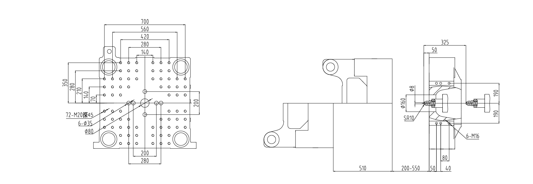
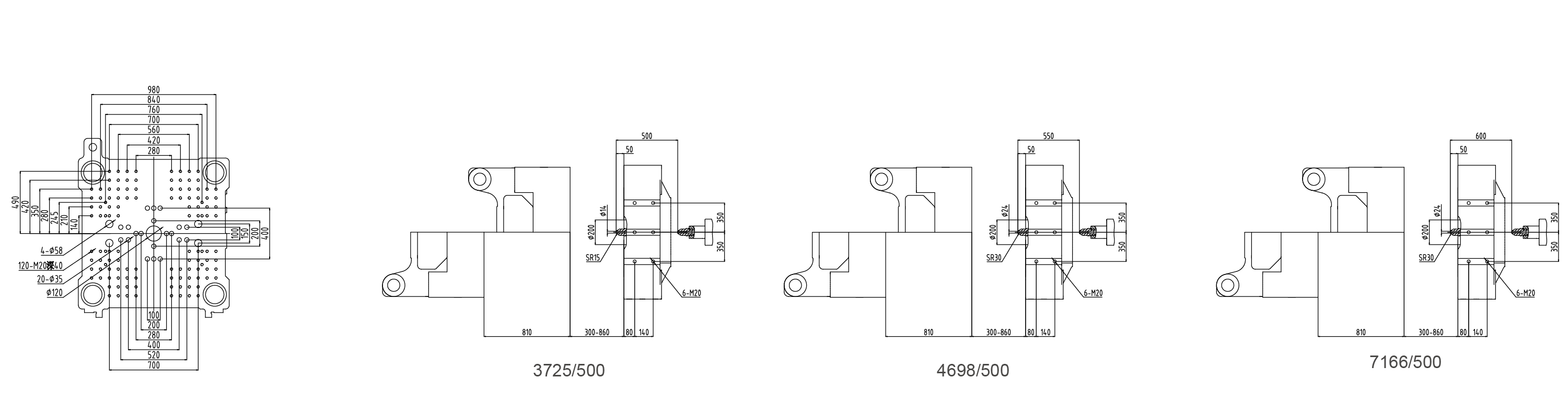
PLT218PET platen and mould mounting dimensions
PLT218PET · Platen dimensionsOpen drawing

PLT268PET

2,680 kN2 injection configurations

Swipe to compare injection configurations

PLT268PET technical specifications by injection unit and screw configuration
ParameterUnit1384/268
AØ 67 mmBØ 75 mm
Injection unit
Theoretical injection volumecm³cm³10571325
Injection weight (PET)gg12901616
Injection weight (PET)ozoz45.557
Injection rate (PET)g/sg/s478599
Screw diametermmmm6775
Injection pressureMPaMPa131105
Screw L/D ratio——25:125:1
Screw strokemmmm300300
Screw speedr/minr/min0–1450–145
Clamping unit
Clamping forcekNkN26802680
Mould opening strokemmmm560560
Platen sizemmmm835 × 835835 × 835
Tie-bar spacing (H × V)mmmm580 × 580580 × 580
Maximum daylightmmmm11601160
Mould thickness (min.–max.)mmmm220–600220–600
Ejector strokemmmm200200
Ejector forcekNkN124124
Power & heating
Hydraulic system pressureMPaMPa17.517.5
Pump motor powerkWkW36.536.5
Heater powerkWkW36.340.7
Temperature-control zones——77
Installation
Oil tank capacityLL480480
Machine dimensions (L × W × H)mm6.95 × 1.82 × 2.356.95 × 1.82 × 2.35
Machine weighttt1010
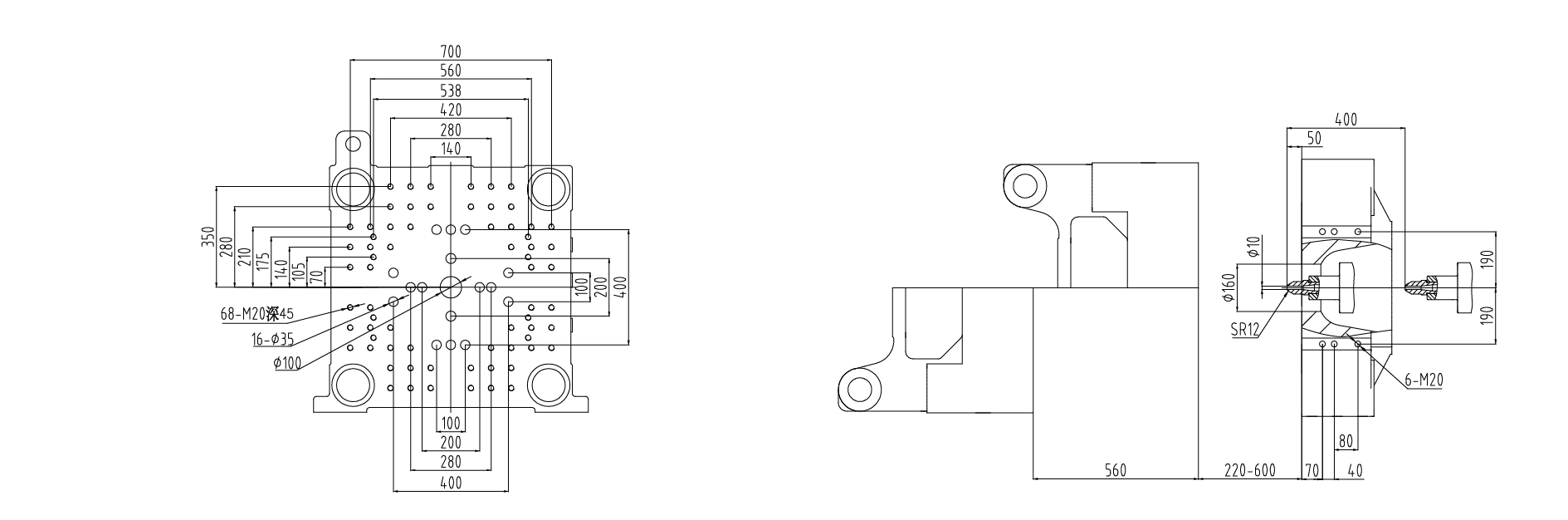
PLT268PET platen and mould mounting dimensions
PLT268PET · Platen dimensionsOpen drawing

PLT320PET

3,200 kN6 injection configurations

Swipe to compare injection configurations

PLT320PET technical specifications by injection unit and screw configuration
ParameterUnit2136/3203725/320
AØ 75 mmBØ 82 mmAØ 90 mmBØ 95 mmCØ 100 mmDØ 105 mm
Injection unit
Theoretical injection volumecm³cm³159019002703301233373678
Injection weight (PET)gg193223183297367340704487
Injection weight (PET)ozoz6881.5116129.6143158.3
Injection rate (PET)g/sg/s580696568633701773
Screw diametermmmm75829095100105
Injection pressureMPaMPa134112138124112101
Screw L/D ratio——25:125:125:125:125:125:1
Screw strokemmmm360360425425425425
Screw speedr/minr/min0–1250–1250–1100–1100–1100–110
Clamping unit
Clamping forcekNkN320032003200320032003200
Mould opening strokemmmm670670670670670670
Platen sizemmmm960 × 960960 × 960960 × 960960 × 960960 × 960960 × 960
Tie-bar spacing (H × V)mmmm680 × 680680 × 680680 × 680680 × 680680 × 680680 × 680
Maximum daylightmmmm134013401340134013401340
Mould thickness (min.–max.)mmmm250–670250–670250–670250–670250–670250–670
Ejector strokemmmm220220220220220220
Ejector forcekNkN151151151151151151
Power & heating
Hydraulic system pressureMPaMPa17.517.517.517.517.517.5
Pump motor powerkWkW50.250.250.250.250.250.2
Heater powerkWkW48.95056.763.770.775.1
Temperature-control zones——777777
Installation
Oil tank capacityLL580580595595595595
Machine dimensions (L × W × H)mm7.70 × 1.88 × 2.407.70 × 1.88 × 2.408.30 × 1.92 × 2.638.30 × 1.92 × 2.638.55 × 2.06 × 2.638.55 × 2.06 × 2.63
Machine weighttt141415.515.516.516.5
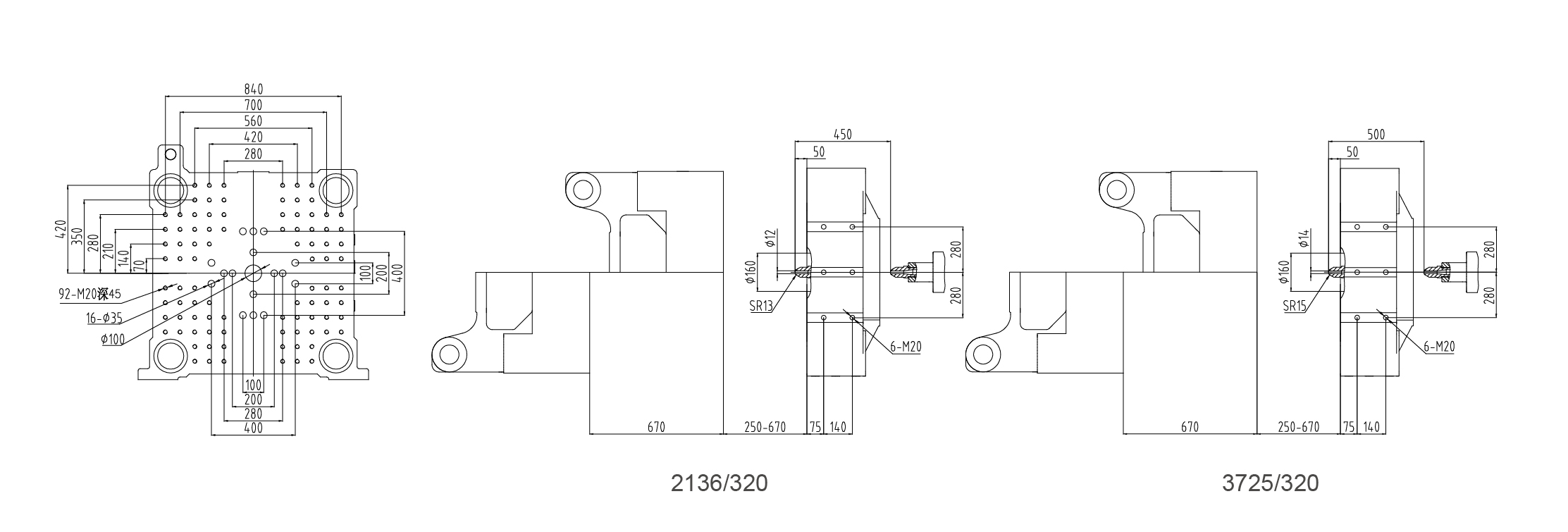
PLT320PET platen and mould mounting dimensions
PLT320PET · Platen dimensionsOpen drawing

PLT430PET

4,300 kN4 injection configurations

Swipe to compare injection configurations

PLT430PET technical specifications by injection unit and screw configuration
ParameterUnit3725/430
AØ 90 mmBØ 95 mmCØ 100 mmDØ 105 mm
Injection unit
Theoretical injection volumecm³cm³2703301233373678
Injection weight (PET)gg3297367340704487
Injection weight (PET)ozoz116129.6143158.3
Injection rate (PET)g/sg/s710791876966
Screw diametermmmm9095100105
Injection pressureMPaMPa138124112101
Screw L/D ratio——25:125:125:125:1
Screw strokemmmm425425425425
Screw speedr/minr/min0–1000–1000–1000–100
Clamping unit
Clamping forcekNkN4300430043004300
Mould opening strokemmmm730730730730
Platen sizemmmm1032 × 10421032 × 10421032 × 10421032 × 1042
Tie-bar spacing (H × V)mmmm760 × 730760 × 730760 × 730760 × 730
Maximum daylightmmmm1550155015501550
Mould thickness (min.–max.)mmmm280–820280–820280–820280–820
Ejector strokemmmm240240240240
Ejector forcekNkN185185185185
Power & heating
Hydraulic system pressureMPaMPa17.517.517.517.5
Pump motor powerkWkW64.664.664.664.6
Heater powerkWkW56.763.770.775.1
Temperature-control zones——7777
Installation
Oil tank capacityLL634634634634
Machine dimensions (L × W × H)mmOn requestOn requestOn requestOn request
Machine weighttt20202020

Request the confirmed installation dimensions for your selected PLT430PET configuration.

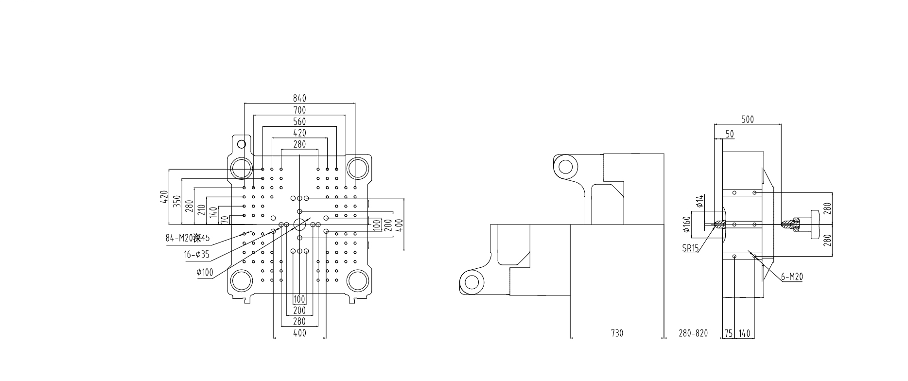
PLT430PET platen and mould mounting dimensions
PLT430PET · Platen dimensionsOpen drawing

PLT500PET

5,000 kN6 injection configurations

Swipe to compare injection configurations

PLT500PET technical specifications by injection unit and screw configuration
ParameterUnit3725/5004698/5007166/500
AØ 95 mmBØ 100 mmAØ 105 mmBØ 110 mmAØ 120 mmBØ 125 mm
Injection unit
Theoretical injection volumecm³cm³301233364111451263306869
Injection weight (PET)gg367340705015550477238380
Injection weight (PET)ozoz129.6143.6176.9194.2272.4295.6
Injection rate (PET)g/sg/s905100398010759891073
Screw diametermmmm95100105110120125
Injection pressureMPaMPa124112114104113104
Screw L/D ratio——25:125:125:125:125:125:1
Screw strokemmmm425425475475560560
Screw speedr/minr/min0–1250–1250–1000–1000–900–90
Clamping unit
Clamping forcekNkN500050005000500050005000
Mould opening strokemmmm810810810810810810
Platen sizemmmm1128 × 11681128 × 11681128 × 11681128 × 11681128 × 11681128 × 1168
Tie-bar spacing (H × V)mmmm830 × 830830 × 830830 × 830830 × 830830 × 830830 × 830
Maximum daylightmmmm167016701670167016701670
Mould thickness (min.–max.)mmmm300–860300–860300–860300–860300–860300–860
Ejector strokemmmm240240240240240240
Ejector forcekNkN232232232232232232
Power & heating
Hydraulic system pressureMPaMPa17.517.517.517.517.517.5
Pump motor powerkWkW31.3 + 36.531.3 + 36.531.3 + 36.531.3 + 36.531.3 + 36.531.3 + 36.5
Heater powerkWkW63.770.7798397.8105.8
Temperature-control zones——777777
Installation
Oil tank capacityLL72572572572510001000
Machine dimensions (L × W × H)mm9.14 × 2.28 × 2.649.14 × 2.28 × 2.649.80 × 2.28 × 2.859.80 × 2.28 × 2.8510.56 × 2.36 × 2.9010.56 × 2.36 × 2.90
Machine weighttt232324242626
PLT500PET platen and mould mounting dimensions
PLT500PET · Platen dimensionsOpen drawing

Technical data: PLANET PET preform series, May 2026 brochure. Specifications are subject to technical changes. Confirm the final configuration, mould compatibility and utilities with your proposal.

Installation reference

Plan the space
around the machine.

Use the drawing and model dimensions for preliminary layout planning. The final installation drawing should include access, auxiliaries and service clearances.

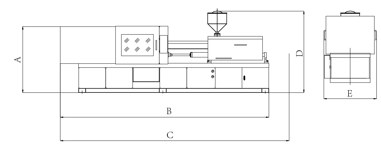
PET injection machine side and front views, with dimensions A, B, C, D and E
Side & front elevations · Refer to A–E belowOpen drawing
View installation dimensionsAll dimensions in mm
Machine dimensions in millimetres, identified by A to E on the drawing
ModelScrew Ø mmABCDE
PLT218PET60 / 6719806250695022301700
PLT268PET67 / 7521506950750023501820
PLT320PET75 / 8222407700820024001880
PLT320PET90 / 9522408300870026301920
PLT320PET100 / 10522408550898026302060
PLT430PET90 / 95 / 100 / 1052350896093402630On request
PLT500PET95 / 10025509140979026402280
PLT500PET105 / 110255098001010028502280
PLT500PET120 / 1252550105601100029002360

Optional configurations

Configure for
your production.

Options are selected to suit the preform, mould and operating conditions. They are not included in every standard configuration.

Discuss the options
  1. 01

    Enclosure & dehumidification

    A fully enclosed clamping area and mould dehumidifier help manage condensation during chilled-water cooling.

  2. 02

    Integrated cooling connections

    A central cooling-water interface keeps mould connections organised.

  3. 03

    Preform ejection detection

    Photoelectric detection checks that preforms have been released before the next closing cycle.

  4. 04

    Colour dosing

    An optional colour-mixing feeder connects to the reserved installation point.

  5. 05

    Infrared heating

    Infrared barrel heating bands are available as an optional configuration.

  6. 06

    Higher-power servo drive

    An increased servo-motor specification can be selected for the production requirement.

  7. 07

    Overlapping cycle movements

    Electric plasticizing or a dual-hydraulic synchronisation system allows plasticizing to overlap with mould opening and ejection.

Plan your preform production

Start with your
preform specification.

Share the preform drawing, weight, neck finish, target output and preferred cavity count. We can help match the machine, mould and supporting equipment.

Request a proposal